Exterior: Rear View
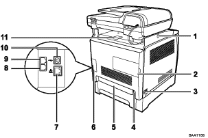
All Types

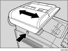
Button for Sliding the ADF
Press to slide the ADF towards the rear of the machine and hold it in that position, if paper output to the output tray is difficult to retrieve.
Memory Cover
Remove this cover to install the optional memory unit.
Power Switch
Use this switch to turn the power on or off.
Power Socket
For connecting the power cord to the machine.
Rear Cover
Remove this cover when loading paper longer than A4 in tray 1.
Cable Cover
Remove this cover when connecting cables to the machine.
Ethernet Port
For connecting the machine to the network using a network interface cable.
G3 (analog) Line Interface Connector (Type 2 and Type 3 models only)
For connecting a telephone line.
External Telephone Connector (Type 2 and Type 3 models only)
For connecting an external telephone.
USB Port
For connecting a USB cable.
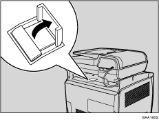
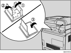
Stop Fences
Raise this fence to prevent paper falling off when printing a large amount of paper at a time. The fence can be adjusted at the A4/Letter or Legal size position.
![]()
Slide the ADF as shown below. Slide the ADF only when the exposure glass cover or ADF is closed. Be careful not to trap your fingers when sliding.

The optional memory unit can be installed in the Type 3 model only.
Raise the fence as shown below to prevent A4- or Letter-size prints from falling off.

Raise the fence as shown below to prevent Legal-size prints from falling off.


